| << . 1 . 2 . |
| Author |
Message |
thefoxes
Member
|
# Posted: 13 Nov 2014 02:02 - Edited by: thefoxes
Reply
Well, we've been brainstorming and we've decided to split this house into three projects to be staged over 5-10 years.
1) 330 sqft split level 12x19.5 efficiency cabin on a partial height basement.
2) The original 16x26(was 24), but timber framed.
3) A final expansion similar the the first expansion at 16x26.
Each house will be staged higher up the slope of the property.
The finished house will have an open span on the main living floor that you can see in one of the attached photos. 70' across from one end to the other, open kitchen/diner, living area, and extended alcove that is at first used as sleeping area in the tiny cabin but becomes living room extension.
iso3.jpg
| 
extension.jpg
| 
Timber.jpg
| 
living_dining.jpg
|
|
|
thefoxes
Member
|
# Posted: 13 Nov 2014 02:05
Reply
Pictures from the first building... still working on the timber frame layout to get it functional / real / not going to collapse / engineer doesn't laugh at me / etc... ;)
Changed the roof a lot sine these renderings were made... it's obviously not a realistic roof plan just wanted to see a gambrel shape on there.
living_space.jpg
| 
sleeping.jpg
| 
laundry__bathroom.j.jpg
| 
timbers.jpg
|
|
|
Steve_S
Member
|
# Posted: 13 Nov 2014 08:02
Reply
This is looking really sharp, especially like the Living Dining Room... Have to say, Love Big Timbers ! Nothing like Mother Natures best in full view.
I'm curious, are you still using Sketchup to render these concepts ?
Now, not to throw a Monkey Wrench into this concept, but have you ever thought about Timber Framing & Cordwood ?
Here's a good resource for info & links to Cordwood Building: Green Home Building They also have a section on Timber Framing as well.
You don't mention the location of your build, but assuming from the pictures with Pines... Somewhere in North Country / Snowy lands... ?
Have you though of skipping the basement altogether and using a Frost Protected Slab Foundation with radiant heating ?
Here's a good article on it from Arizona Edu in PDF frost-protected shallow foundation (FPSF)
FPSF is becoming quite common in Canada and can serve you in a few ways... It's also a heck of a lot cheaper to do than a full excavation & basement and minimizes environmental impacts.
|
|
thefoxes
Member
|
# Posted: 13 Nov 2014 11:13
Reply
cordwood is a little too rustic for me, and if you've ever been in a house with radiant heat you'd find that it's just awful... awful. I plan on having fireplaces for heat in the winter, and I love basements.... with the slope of the property it's pretty essential anyway.
I"m using sketchup with the free twilight rendering plugin to make the detailed renderings.
|
|
Steve_S
Member
|
# Posted: 13 Nov 2014 12:00
Reply
Hmmm, I've had good experiences with radiant heating... I guess it depends on the configuration & setup.
I should have taken the time to learn Sketchup I suppose... I use a different piece of software called Home Designer Pro 2015 but had to manually add certain build materials for cordwood. Although it has come in handy for the Cabin Build I'm doing now.
We are also building on a South Facing Hill but luckily it has 3 natural "steps" or terraces so it accommodates us nicely. Was hard to see all that when all the bush, scrub and everything was still there.
Your plan looks terrific, looking forward to seeing more as you continue the progress.
|
|
thefoxes
Member
|
# Posted: 13 Nov 2014 12:35
Reply
Sketchup is incredibly easy to use, but not as accurate as some programs... unless you watch what you're doing. There is a wealth of dynamic compoents for things such as windows, doors, stud walls, plywood, etc... that scale or have user assignable variables for width height etc...
The key to sketchup is using groups, compnents, etc... to keep surfaces from sticking to each other.
The majority of custom surfaces you make start with a 2d surface you draw, then you push/pull to create 3 dimensions. I feel it's a lot like a video game, which appeals to me. I grew up living in a 3d gaming world ;)
Best part if it all is that sketchup is free. That's a price I like.
Our property is in the Pacific Northwest, about 250' from a river in Clark County. It's a lovely spot. I grew up there many moons ago and I look forward to my kids playing there as they grow up. It's a north facing lot in a valley... not the best lot for sun exposure. So I went for the west facing layout.
|
|
thefoxes
Member
|
# Posted: 13 Nov 2014 15:58 - Edited by: thefoxes
Reply
Talking to a local timber framing company today, going to bounce ideas off them and see what they think about the staged build.
Here's another image worth peaking at, it's a 3d representation of the floor plan. Lots of open areas in the final building, wide expanses even though the house is narrow. Designed to work with the land instead of against it.
It amazes me how this plan has progressed over time with the help of 3d rendering. I can't imagine how people thought up their homes before such technology existed!
I've intentionally left the floor plans with little detail because the timber framing lets me choose exactly what i want for each interior space at a later point in time... Probably going to put most of the kids bedrooms and full bathrooms in the lowest floors since it's all rolling downhill anyway.
|
|
thefoxes
Member
|
# Posted: 21 Nov 2014 22:43 - Edited by: thefoxes
Reply
Not much been going on lately. Talking to a timber framing company about the project... that will develop over the next year or so into a more solid timeline.
Here's two concept drawings we've done for the final building. It's essentially three small cabins tied together. Each to be built as separate projects over 5-10 years and tied together.
Rendering of the living room included because we wanted to see how tongue and groove would look.
|
|
|
thefoxes
Member
|
# Posted: 22 Nov 2014 14:16
Reply
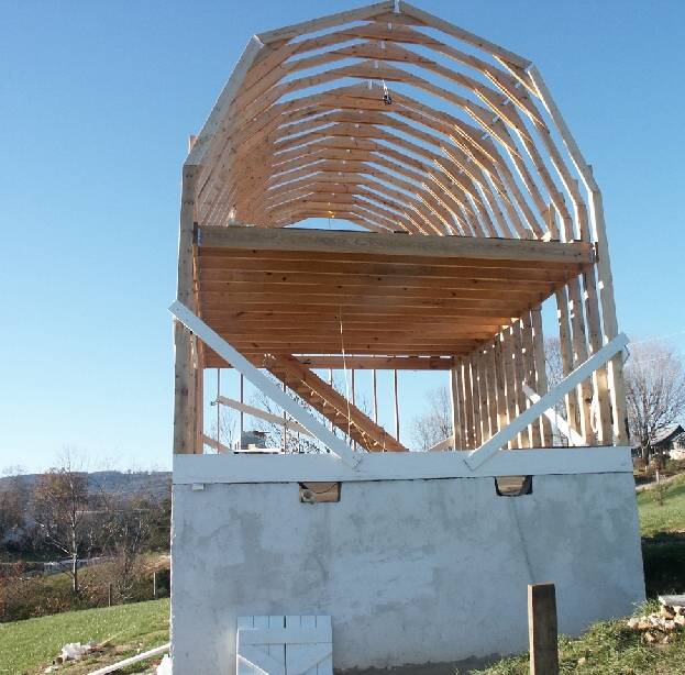
I can't describe how much I've grown to hate building codes. Specifically the requirements for staircases. Due to IRC requiring 80" headroom from the angled line created by the nose of each stair tread I had to expand the footprint at least 2' on the width, decided to do it to both sides to keep the consistency in building size across the three building projects. First project now has dimensions of 16'x19'10".
The framing is still a bit weird.... it's like trying to saddle the loft space partway down the natural location to create headroom....
partial_timber_1.jpg
| 
partial_timber_2.jpg
| 
partial_timber_4.jpg
|  |
|
|
Don_P
Member
|
# Posted: 22 Nov 2014 16:25 - Edited by: Don_P
Reply
The stairs need more work. The winders cannot come to a point, no narrower than 6" at the narrow end in the clear width of the stair, 10" min at the 12" walkline.
The angled tension strut at the top plate to floor in timberframe would be effectively useless at resisting thrust in that short pony wall.
|
|
thefoxes
Member
|
# Posted: 22 Nov 2014 16:27
Reply
Thank you. I just threw the stairs in there from someone else's sketchup model to get an idea of where I want the stairs.
That knee wall is the bane of me... what would be the best way to handle that situation? King post to a ridge beam so no load goes on the knee wall? A bolt from the bottom plate of the knee wall through to the bottom of the timber they rest on?
|
|
Don_P
Member
|
# Posted: 22 Nov 2014 17:59
Reply
This is one compact set I did.
timbertoolbox.com/sketches/winders.skp
Easiest fix is to lose the kneewall and set the rafters at floor level, possible?
|
|
thefoxes
Member
|
# Posted: 22 Nov 2014 18:13 - Edited by: thefoxes
Reply
No... sadly, that would make the headroom untenable.
I've seen a gambrel on a wall like that before and don't see support... I'm wondering if the geometry forces the load straight down.
probably going to have to add this to the list of details the engineer/architect firm will have to figure out.
|
|
Don_P
Member
|
# Posted: 22 Nov 2014 19:43
Reply
It will need professional design. The TF company will also need to be involved in the design.
I have seen papers where this was analyzed as a 3 hinged arch. Here's what I was remembering;
http://www.csbe-scgab.ca/docs/journal/21/21_1_47_ocr.pdf
Notice this was for low human occupancy farm buildings, they bumped the allowables by 25%.
An arch does produce thrust, Notice HL and HR, the horizontal reactions in the paper's first fig.
Do notice the difference between your short pony wall and the extended studs of the picture, basically they have end loaded vertical beams overhanging the support of the upper floor. That building was designed by an amatuer, be careful of what you copy. Just for more grist, imagine extending his floor joists out beyond the wall and extending the steep rafters down to where they tie to the cantilevered joists. The horizontal load is resisted by the joists and the vertical load is carried by the kneewall... and I am not an engineer so take that with a big grain of salt.
|
|
Fire18
Member
|
# Posted: 16 Dec 2014 20:02
Reply
My cabin in Upstate NY. Started small ended up 24X32.
|
|
| << . 1 . 2 . |
