| . 1 . 2 . >> |
| Author |
Message |
thefoxes
Member
|
# Posted: 17 Oct 2014 05:11pm - Edited by: thefoxes
Reply
Well, not exactly a "small cabin," but a 16x24 cabin on a full basement with a finished attic (I have kids and we want this to be our principal residence.)
I've been working on a Sketchup 3D model of a cabin my wife and I hope to build in a year or so.
2x6 walls (required by code,) 2x12 floors 16' span, 2x10 Gambrel Rafters (insulation depth to meet code with 2" rigid on outside), 12" basement walls (maybe overkill?) basement is half out of ground on two sides. Drain tiles and sump under slab.
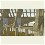
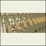
Here are a few shots of the cabin, I was wondering if someone could look at the rafter setup and tell me if the knee wall with cross bracing to joists was too much. The rafters are sitting on top of a secondary stud plate attached to the floor joists. Rafters on joists instead of top plate, for the extra head room. Attic has full 2x12 joists on 16" centers, same as first floor. I want to use it for heavy storage and/or small sleeping quarters if we have more kids than we are expecting! 
Side Elevation:

Front Elevation:

Dimensions:

Basement:

First Floor:

Attic:

Gambrel Rafters:

Knee Wall:

|
|
thefoxes
Member
|
# Posted: 18 Oct 2014 01:10am
Reply
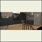
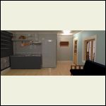
Here are a few renderings...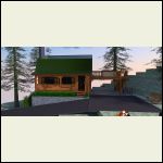
front.jpg
| 
living_room.jpg
| 
kitchen_2.jpg
|  |
|
|
Don_P
Member
|
# Posted: 18 Oct 2014 01:53pm - Edited by: Don_P
Reply
The lower kneewall conglomeration is counterproductive. It is incorrect to put the rafters on top of the floor rather than tieing the floor joists directly to the rafter tails. The 2012 building code now includes a drawing that limits the rafter birdsmouth notch to 1/4 of rafter depth, you're a good bit deeper than that would allow, not saying I agree with that code drawing. But, mentally follow your rafters down to where they would intersect the top plate, you're mighty close or right on track to have at least minimum 1-1/2" birdsmouth bearing on the top plate. Then offset the joists and run them alongside of the rafters and everybody should be happy.
The blocking in between rafters in each bay interrupt ventilation (if a vented space) and is not commonly done. Although if it is vented foam on the outside isn't going to do much so probably not understanding the insulation plan. The actual gambrel structural is beyond me, I would see if a ridgebeam would carry the roof and hang it from that. Failing that an engineer could also design it.
I don't believe you are tall enough upstairs yet, maybe bump out to 18" to pick up more height, I'd also check with the local truss shop and see if they can design a truss that does roof and floor.
Stack the circular stairs? I'd put a good set to the deck for stocking the attic and emergency escape.
Nice drawings, not sure if you've explored the sandbox features for site drawing, it smooves out the contour intervals.
|
|
thefoxes
Member
|
# Posted: 18 Oct 2014 02:30pm
Reply
Thanks for the info. I'm not going to vent the attic space in accordance with http://publicecodes.cyberregs.com/icod/irc/2012/icod_irc_2012_8_par100.htm.
I appreciate the info on the birds mouth. I'm a little curious as to how they support a vaulted ceiling with no ceiling joists whatsoever following your logic that the rafters have to be tied to the joists. I've seen a number of discussions of contractors using the knee wall as a support structure with purlings on a grambrel.... who knows.
I'm probably just going to have to have an engineer work up and stamp a set of rafters to meet the needs of the house.
|
|
Don_P
Member
|
# Posted: 18 Oct 2014 08:38pm
Reply
I'm a little curious as to how they support a vaulted ceiling with no ceiling joists whatsoever following your logic that the rafters have to be tied to the joists.
Scroll down to R802.3.1 for the background behind that logic.
http://publicecodes.cyberregs.com/icod/irc/2012/icod_irc_2012_8_sec002.htm
A gambrel is really outside of prescriptive "codebook construction" so for a residence an engineer would be the right way.
|
|
thefoxes
Member
|
# Posted: 18 Oct 2014 09:02pm
Reply
I think I'd have to agree with your logic. I really do need an engineer for something as important as an unusual roof layout.
I prefer to keep it below the height requirements for habitable space and keep it climate controlled storage for tax purposes... plus it really looks nice on the house when it's NOT obvious there is a usable space up there. Otherwise it's just a glorified two story barn.
|
|
thefoxes
Member
|
# Posted: 20 Oct 2014 02:37pm
Reply
Well, I've put my brain to redesigning it a bit more and pouring over current and previous versions of the IRC. I'm sure I will still need an engineer's stamp, but at least he won't have to change as much about the layout.
Source: http://www.iccsafe.org/iccforums/Pages/default.aspx?action=ViewPosts&fid=11&tid=9924
In accordance with the 2000 version of the IRC (since the current doesn't seem broach the topic,)
2000 IRC
R802.6 Bearing, each rafter shall have not less than 1.5" bearing on wood.
R802.7.1 exc. Notches on cantilevered portions of rafters are permitted provided the dimension of the remaining portion of the rafter is not less than 4-inch nominal and the length of the cantilever does not exceed 24".
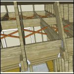
So I reduced the birdsmouth significantly, and upped the rafter size to 2x12 to give more meat. Attached the joists to the rafters with a metal plate similar to how trusses are joined, and added an additional rafter tie made from a 2x6x24 cut down to size (17' roughly.) Lastly placed hurricane ties from the rafters to the top plate on both sides. Went to 24" spacing after upgrading everything to 2x12... placed blocking and herringbone supports between ceiling joists.
It will be mountains cheaper to use the additional rafter tie made of 2x6 as opposed to a larger 2x12... goodness a 2x12x greater than 16' is expensive.
Any more suggestions? I'd like it to be overbuilt, very strong.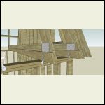
rafter.png
| 
rafter2.png
| 
gussets.png
| 
bracing.png
|
|
|
luther
Member
|
# Posted: 20 Oct 2014 07:35pm
Reply
Nice design. I am by no means an expert but your joists look like they will be acting as rafter ties. Why do you think you need an additional one? may save you some money. may save you some money.
My cabin has attic trusses for part of the roof and the joist is acting as the tie.
Not trying to be critical, just curious
Cheers
|
|
|
thefoxes
Member
|
# Posted: 20 Oct 2014 07:58pm - Edited by: thefoxes
Reply
I wasn't sure if joining with a plate alone was considered sufficient... probably is overkill.
|
|
Don_P
Member
|
# Posted: 20 Oct 2014 08:18pm
Reply
Rarely would I admit to agreeing with the disagreeable old cuss but George Roberts is right on the ICC thread.
Use TJI's for the upper floor/rafter tie, there is no "ding" for going over 16'. It looks like a 9-1/2" deep I joist could do the 16' span if spaced on 16" centers. The TJI runs alongside the rafter, a web filler and face nail the joist to the rafter base. The rafter foot does need to have a minimum of 1-1/2" bearing on the plate. The 17' 2x6 goes away, the metal plates go away, one of the hurricane ties goes away (do not put hurricane ties or angles on both sides of a member without an engineer's blessing, doubling up can weaken the connection)
The rafter doesn't need to be a 2x12 structurally, what is the reason for the depth?
As long as I'm being highly opinionated, X bridging is nothing but a prebuilt squeek. Blocking is not required for the joist (if solid sawn) if the ends are laterally restrained, the centerline row of solid blocking is not a bad idea. If using tji's follow manufacturers specs (on any proprietary engineered product)
No double rafter at the gables, probably a dropped wall with lookouts passing over it to the overhang's fly rafter.
Without compromising strength, that should have just saved enough to pay for going to 16" centers with enough left over to take the wife to dinner 
|
|
thefoxes
Member
|
# Posted: 20 Oct 2014 08:28pm
Reply
Wow! Great info, thank you!
I want to avoid I-joists because I've seen what happens to them in a fire.... absolutely terrifying. Beside that, I intend on using the space for heavy storage. The full plans include a 4'x4' casement window at the end that opens to the deck so I can move large items in and out of the attic. I'm probably wrong, but I thought 2-12 joists in the ceiling would provide a base solid enough for anything I could possibly want. Plus, honestly, what is it like $300-$500 in lumber? That's not much compared to the cost of the whole project. Heck, the impact fees *cough* robbery *cough* are around $15k just for the *right* to build on my own land. :/
I wanted the 2x12's on the rafters so I could over-insulate and because they require huge amounts of insulation in the Pacific Northwest on roof assemblies.
Such good info on the only one hurricane tie! I had no idea... I'm just shooting in the wind here and reading through code books. I'm trying to get my 3d model as close to a real plan as possible so I can have an engineer or architect go through and make real plans from it. I've gotten quoted down to $500-1000 to finish the plans if I basically do all the work for them. :/ The county we plan on building in has a real hair up it's ......, they want an engineer or architect's stamp on everything or you don't get to build.
Off topic: Who is George Roberts?
|
|
Don_P
Member
|
# Posted: 21 Oct 2014 10:14pm
Reply
George is a good engineer of the 2x4 between the eyes school. He was the one who posted on the ICC forum thread that a birdsmouth is not a notch in the sense of the code notching rules. I agree. Notice that between that time ('04) and now the code has been changed to reflect the misinterpretation.
The 16' 2x12 floor joists will act as ties if they can get a good enough bite between them and the rafter. I'd run them alongside and pull the rafter inboard as much as possible, if needed put a simpson strap between them along the joist to develop length and wrapped over the rafter. At that steep pitch there really isn't much horizontal thrust to restrain. Be receptive to the engineer's suggestions as well.
|
|
thefoxes
Member
|
# Posted: 5 Nov 2014 04:58pm - Edited by: thefoxes
Reply
Well, wrapped up the design for if we go stick built...
I've been putting a lot of thought into timber framing and I've been pouring through different iterations of the floor plan until I found exactly what we wanted.
After a while I stumbled upon the fact that I was laying out the interior very similar to a golden ellipse, and that the 16x24 shape was very near to a golden rectangle 16x25.89.
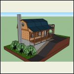
I redesigned the exterior footprint to more closely resemble the aforementioned dimensions and came up with this. I think it has a slightly more pleasant appearance.
Here's a quick video: URL
An interesting detail I found out while scouring through building code is Washington state allows for a ladder accessible loft space as long as it is under 200sqft. Instead of a full attic I'm now aiming to leave the ceiling above the living space cathedral style and put a loft above the entryway/bathroom/kitchen. Again, it fits neatly inside the natural geometry of the golden ellipse.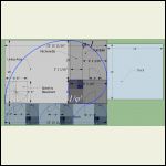
cole_witter_blueprin.jpg
| 
cole_witter.jpg
|  |  |
|
|
thefoxes
Member
|
# Posted: 5 Nov 2014 05:04pm
Reply
One thing I'm having trouble deciding on is what to do about the foundation.... the way I would *like* to have things, there will be a small retaining wall where the driveway is at and an open air storage under the front porch. That way there's no water seepage on that 25' section of basement wall. The front section is walkout, giving no water on that side, and the back is also open with an egress door. Essentially the basement would only be in contact with earth on the very back wall under the deck/carport area.
So, I see that I have three options.
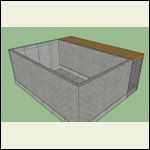
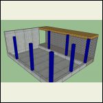
1) Fully poured basement walls, even though they're not down in the earth.
2) Concrete footer with one full height poured wall, everything else done with grout filled block.
3) If I go timber frame (which yes I know is expensive, but for such a small house negligible, less than the cost of my stupid impact fees.) I could extend the timbers all the way down to the concrete footer and use whatever close in method is cost effective (hay bale, sips, advanced framed wall, etc...)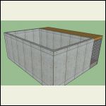
full_basement_pour.j.jpg
| 
use_blocks.jpg
| 
extend_timbers.jpg
|  |
|
|
Don_P
Member
|
# Posted: 5 Nov 2014 09:17pm
Reply
with the grades you have I like the concept of option 3. I would return the poured walls around both framed sides by 4-8' to brace the adjacent poured walls. In basements under timber frames I've made those extended timbers in the walls out of ganged up 2x8 studs under the posts above, buried within the wall framing. If there are posts needed out in the floor area those can be solid sawn timbers. This is cheaper and saves some money for the timber frame above. Remember the post loads should stack over each other from floor to floor. I'm not a real fan of trying to waterproof a porch floor, but we just talked about it on the current job.
|
|
thefoxes
Member
|
# Posted: 5 Nov 2014 09:31pm
Reply
Okay, so I wasn't out of my mind thinking option #3 would work. I was wondering about pouring the wall out on each side to support any load from the backfill, etc.... good info. Thank you.
The slope on the property is really nice, and with some well placed bushes it will create the illusion that the walkout basement is shorter.
Any clue how much a 16x26 gambrel timber frame with a 5'4" porch will run me? I've seen a wide range of prices, some expensive, some border-lining on mental illness. Not sure what to expect in the Pacific Northwest... one place even advocated having a frame shipped if the price difference was copacetic to the process.
|
|
Don_P
Member
|
# Posted: 5 Nov 2014 10:09pm - Edited by: Don_P
Reply
Are you opposed to framing it yourself? A local sawyer could probably provide the timbers. If you didn't want to tackle the joinery you could have it designed as a post and beam with timbers, metal plates and bolts... hardware exposed or hidden. We do tend to think of timberframing as high art nowadays, a few generations ago it was simply framing, accomplished by regular carpenters, farmers, and anyone else who wanted a house. I've also kicked around the idea of built up timbers of 2x material 4 or 5 plies thick with joinery produced by interweaving the plies where the built up timbers connect.
|
|
thefoxes
Member
|
# Posted: 5 Nov 2014 11:05pm
Reply
Unfortunitelly that's not an option.... I'm an early retired soldier, nerve injury in my dominant arm. I can hold basic objects, work a few small tools, but I can't do real work with my right arm. My greatest tool will be my mind, and amassing the knowledge required to design a cost effective and beautiful home.
Such is life. 
|
|
thefoxes
Member
|
# Posted: 7 Nov 2014 02:42am
Reply
Don_P, how do you feel about scarf joints in vertical members? I'm pouring through a few timber framing books and I see that a number of times a tall post was extended with a scarf joint instead of using a single post. This seems like a nice method to me to be able to construct the basement portion of the timber frame first, then the first floor on top of that. No need for a crane as all the members would be around 155.55 pounds... (assuming douglas fir with an average weight of 35lb per cubic foot, 8/12^2*10' average member length.) If I could effectively utilize that method, this would be buildable by my family. No need for more than one professional on site, no need for a crew... just an engineer's stamp to get the county on board.
It's nowhere near done, but I'm working up a 3d model of the timber frame on top of the walkout basement. I still need to figure out the floor joist, rafters, and porch...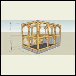
Timber.jpg
| 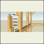
scarf_vertical.jpg
|  |  |
|
|
thefoxes
Member
|
# Posted: 7 Nov 2014 02:43am
Reply
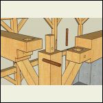
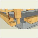
Here are a few more joints I've tried to recreate in sketchup based on drawings in a few books. Open to suggestions for better connections or a better way to handle the floor (since I"m clueless so far on that part, too in depth in the book have to study it.)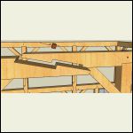
scarf_top.jpg
| 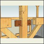
central_timbers.jpg
| 
top_joinery.jpg
| 
sill_plate.jpg
|
|
|
Don_P
Member
|
# Posted: 7 Nov 2014 07:07am
Reply
First, Thank You for your service.
On the TF Guild website there is a free download of Jack Sobon's "Historic American Timber Joinery", although it looks like you're in their red design book.
You can scarf the posts. My inclination is more towards platform framing the basement, this can be heavy timber, then restart the posts on the main level. The floor diaphragm provides lateral support for this and the pieces are easier to work with. I'm not a great fan of scarfs in beams, I'd check them as beams overhanging posts rather than only using the less conservative method of viewing them as continuous beams. The AISC manual also has beam formulae for these conditions in steel beams.
The floor joists... I'm not a fan of drop in dovetails or anything that breaks the top or bottom fibers of the beams. The simplest and stronger is to simply place them on the unnotched beam with blocking between. If you do want them in the plate then something along the lines of a tusk or soffit tennon would be kinder to the beam by mortising into the neutral axis. C.A. Hewitt's "Historic English Carpentry" has a good section on the evolution of these joints.
|
|
thefoxes
Member
|
# Posted: 7 Nov 2014 09:55am
Reply
Thank you for the tip. I was reading a Jack Sobon book, but not the one you mentioned... great resource!
The floor sure is a hairy area. I would think at the very least I would need a tie beam between the two tall posts on each side of the 26' stretch.
|
|
Don_P
Member
|
# Posted: 8 Nov 2014 09:56pm
Reply
Maybe I'm not seeing the issue, are the floor joists not providing that tie?
Attached is a pic of the joist tennon (b) I was talking about above if you do want to tennon the joists in. ca ~1450AD
|
|
thefoxes
Member
|
# Posted: 8 Nov 2014 10:08pm
Reply
Is that a tusk tennon in part (b)? That would certainly tie everything together well.
I was having trouble figuring out how I would span the 16' without supports in the basement. My wife hates the idea of any support posts... she's okay with beams, just not posts.
I was even floating the idea of doing timber hybrid and using 2x12's to span the 16' and tie everything together with a double rim joist bolted to the girders...
This is where my lack of knowledge really becomes an issue. All of the timber framing books I can find in ebook format are very non-specific about the layout of girders, floor joists, summer beams, etc... and it doesn't seem like they are designed to be compliant with the deflection requirements of the IRC.
|
|
Don_P
Member
|
# Posted: 9 Nov 2014 08:40am - Edited by: Don_P
Reply
Yes, that is a type of tusk tennon. Do contemplate how many hands it would take to insert those as the frame goes together.
Many are not, but easy enough to check. You can easily mix and match heavy timber components with a stick framed structure just bear in mind that a heavy timber frame collects and delivers heavy point loads to relatively few locations where a typical stick frame uniformly distributes load. make sure you follow the load path of the timberframe components to the foundation. I've built a conventional basement under a timberframe using 2x12 joists, etc. On another they wanted timberframe elements in the main public areas in an otherwise conventionally framed house. We did timberframe in the entry and the greatroom roof while stick framing everywhere else. That house had engineered open web floor trusses spanning up to 20'. So it isn't really an all or nothing situation, you can mix and match.
Another pic of the D'Arcy Chantry. In the foreground notice that the joists overhang the front wall to form the upper floor jetty and at their back end they insert into the tie beam with that housed tusk tennon. Notice that front area is basically platform framed, not at all uncommon. Don't copy the roof  ... but then, it's over 500 years old. ... but then, it's over 500 years old.
|
|
thefoxes
Member
|
# Posted: 9 Nov 2014 10:25am
Reply
That is a lovely use of corbels in the front and an incorporated cross in the gable... lovely.
Even if for some reason we decide to go back to stick built, which is looking less and less likely in the rear view mirror, reading these timber framing books from the 70-80's is giving me a different perspective on building a home.... I'm starting to get a real appreciation for building something that lasts, building in stages as you have the money, etc...
I never want to be a slave to the bank again.
|
|
Don_P
Member
|
# Posted: 9 Nov 2014 06:07pm - Edited by: Don_P
Reply
The incorporated cross in the gable and the posts on the tie beams inside is what I was talking about not copying, or, if you do, do it in the next evolution of roof framing, a king post truss. This roof was framed with crown posts, which obviously can work for the long haul, but is not particularly efficient. Look at the center bent for a minute. The tie beam is a large simple beam spanning between posts with serious bracing. The post on top of it is considered to be delivering a point load from the roof system above that it supports by way of the collar beam and its' bracing. The crown post is a compression element. Look at the gable ends and their bracing with this thought in mind.
The next evolution had the same english tying joint at the rafters' feet/tie beam connection. The tops of the rafters pinched a kingpost between them and that post dangled down from the peak to tennon through the tie beam which it supports at midspan. Instead of bearing down on the tie, the kingpost, or as they would have called it more descriptively. the kingrod, helps hold the tie beam up. A kingpost is a tension element, it could be a cable or chain. The tie, supported rather than supporting, can then be much lighter, or it can support more load.
These kingpost trusses were incorporated in a stick frame building and roof. From truss to truss there is a built up ridgebeam capable of spanning betwee trusses to support the common stick frame rafters.
[img]http://i180.photobucket.com/albums/x109/windyhilll/Beyer8_15_11001.jpg[/img ]
this is the kingpost
[img]http://i180.photobucket.com/albums/x109/windyhilll/Beyer8_15_11004.jpg[/img ]
along the way during that longwinded side trip I came across the attached pic saved off the web some time ago.
|
|
thefoxes
Member
|
# Posted: 9 Nov 2014 06:42pm - Edited by: thefoxes
Reply
Seeing the rest of the info on that photobucket I'd say you've swung a hammer more than once or twice. The area looked familiar and then I realized I've seen those mountains before.
I still have a little house in Appalachia, VA, and spent a great deal of time in Johnson City, TN when my son was born premature. Poor house has a leaking roof and has been empty for years. Built over 100 years ago, on a hand cut hokie stone foundation, structural brick, with wormy chestnut floors... what a waste.
Southwest Virginia sure does have bitter winters.
|
|
Don_P
Member
|
# Posted: 9 Nov 2014 08:04pm
Reply
My Dad was a builder. He built in what we would now probably call plank and beam style. Heavy timber roofs with structural decking over them. As an aside, I suspect in the near future we are going to see heavy timber sheathed in CLT's, cross laminated timber sheathing. I do like big timber but it is generally more expensive.
Your mountain place sounds like a beautiful old house and yes we can have fairly tough winters. I seem to enjoy them less, my internal furnace doesn't seem to put out like it used to  Still and all, I've built around a fair amount of the country and always seem to be drawn back to these hills. Still and all, I've built around a fair amount of the country and always seem to be drawn back to these hills.
|
|
thefoxes
Member
|
# Posted: 9 Nov 2014 08:33pm
Reply
There was a lot of nice framing done in the owner/manager houses of old coal camps in that region. Incredible stuff.
|
|
| . 1 . 2 . >> |

