|
| Author |
Message |
rugercpl
Member
|
# Posted: 27 Jul 2012 07:24
Reply
I have an off grid cabin that's wired throughout but gets its only power right now by a generator hooked in to the electrical panel box in the cabin. I would like to tie in a solar power system so all the outlets in the cabin get their power from solar....with respects to using only as much solar electricity as the system can handle.
Can solar power systems be wired into standard household electrical panel boxes?
|
|
cman47c
Member
|
# Posted: 27 Jul 2012 08:11
Reply
Yes. With the solar system you will have an inverter that must match the voltage of your existing electrical box and you will need some sort of switching arrangement to select either the generator or solar supply. Grounding can be a little tricky with the inverter depending on how your existing system is setup.
|
|
rugercpl
Member
|
# Posted: 27 Jul 2012 08:51
Reply
Even with nothing turned on plugged into an outlet, can power be drawn (and drained) from the battery?
. is it neccesary to throw the main breaker to the off position while away from the cabin?
|
|
MtnDon
Member
|
# Posted: 27 Jul 2012 10:44
Reply
The proper way to do this is with a transfer switch. There are manual varieties and automatic ones. They have two inputs and one output. One input would be the generator in this case and the other would be the inverter. Using a transfer switch makes it impossible to accidentaly connect the inverter and generator at the same time.
An automatic transfer switch would be set up to automatically switch from the inverter to the generator whenever the generator was started. Good auto transfer switches will have a programmable delay between the generator starting and the switch activating. That let's the engine get warmed up before placing a load on it.
Trying to do this any other way is asking to have equipment damaged or worse someone get killed.
|
|
MtnDon
Member
|
# Posted: 27 Jul 2012 10:49
Reply
Quoting: rugercpl Even with nothing turned on plugged into an outlet, can power be drawn (and drained) from the battery? . is it neccesary to throw the main breaker to the off position while away from the cabin?
Most inverters consume power when idle. There are some that have a standby setting basically shuts it off but still uses very small amount of power. Much like a TV with a remote; they use small amounts of power when off. Cheaper inverters do not have standby and are always using noticeable amounts. So to prevent unwanted drain on the battery the inverter must be turned off or disconnected from the batteries. No real need to pull the main switch/breaker in the AC service panel when the inverter is completely off or disconnected from the battery.
|
|
GomerPile
Member
|
# Posted: 27 Jul 2012 13:28
Reply
You should decide if you really want to keep all those outlets AC powered or not. Switching to a DC system would allow you to charge up a battery with your solar panels and use the power anytime of the day.
When the sun is not out you can use the generator to charge the batteries.
Both ways have benefits and drawbacks.
|
|
wakeslayer
Member
|
# Posted: 27 Jul 2012 17:48
Reply
My opinion is that you should wire it AC, and use an inverter. I would never consider undoing the AC to switch over to DC. In general, modified wave inverters are not that expensive. I think I paid $300 for an 1800w unit, that is plenty for most cabiny stuff.
|
|
MtnDon
Member
|
# Posted: 27 Jul 2012 18:02
Reply
DC may be okay for very small systems; 2 batteries and a few lights. IMO, anything larger should be done in 120 VAC. You will find varying opinions on that. You have a much wider choice of products with 120 VAC.
|
|
|
Parrotdog
|
# Posted: 22 Nov 2012 12:25
Reply
MtnDon
You seem very knowledgeable on this subject.
If you can help it would be much appreciated. I have a home off grid. I am using an out back fx system to manage the panels, battery bank, and invert the power. I also have a generator and an Asco auto transfer switch for back up power during extended cloud cover. I need to have this completely auto for I am not at the residence full time and there is a need for power to supply security equipment, lights,satellite communication, etc.
My issue is separating the input from the output on the inverter / charger when power flow is controlled by an auto switch. The FX system comes with a manual transfer switch which isolates the power-in busbar and it has a circuit breaker to protect the power coming from the power-in busbar to the power-in on the inverter allowing for battery charging. If I remove the manual transfer switch and wire the inverter to the preferred power-in on the switch than I have a problem ( or not?) with power from the inverter cycling back to the power-in on the inverter while the transfer switch is in the preferred position. The breaker that protects incoming power to the inverter could have a relay in series with it but would have to toggle at the correct time when switching to the back up generator.
Any suggestions or a diagram that addresses this situation?
Thanks Mark
|
|
MtnDon
Member
|
# Posted: 24 Nov 2012 15:14 - Edited by: MtnDon
Reply
Assuming this is totally off grid, no grid tie power at all.... (this is pretty much what our system is).
There would be a standard power service panel that feeds the home circuits. The power into that would come from the output of an automatic transfer switch.
The auto transfer switch has two inputs just like a manual switch. The "normal" one which would be from the inverter or stacked inverters. I call it normal as the power applied there goes straight through as the normal setting. (The batteries feed the inverter and the inverter in turn feeds the house.)
The "alternative" power input to the automatic transfer switch would be from the generator. The switch should have a delay built in so that when the generator starts it has time to warm up and stabilize before being asked to work hard at supplying the needed power. At least that is nice to have but not mandatory. Handy in cold weather though... my generator will refuse to work well until warmed up, so I give it 5 minutes in winter and reset to 1 minute in late spring.
There would be an automatic generator start and shut down system. When the battery voltage would reach a pre-selected low voltage point, for a pre-determined time interval the system would start the generator. The generator would charge the batteries via the charger built into the inverter(s) and supply the AC power to the house. The charge system would then take the batteries through the bulk and absoption charge stages before shutting off the generator. While this is going on the inverter does not supply power to the house as it is cut out of the circuit by the automatic transfer switch.
A manual transfer switch works in a similar manner, but can not be used with an automatic generator start.
With either automatic or manual switches both the hot legs and the neutral legs of the power must be switched, not just the hot legs. By switching all legs there is isolation that is complete.
Some auto start systems are easier and cheaper to implement with some generators. A lot depends on the generator.
|
|
Parrotdog
|
# Posted: 25 Nov 2012 20:22
Reply
Thanks for the reply. Everything you have written is how I anticipate the system working other than power going back into the inverter/charger. My out back inverter/charger has a connection for power that would connect to the primary source on the transfer switch and another for power to be accepted from the circuit panel which of course is connected to the load side of the transfer switch. Therefore power is connected to the incoming power connection on the inverter reguarless of the power source unless there is some sort of relay preventing it. Dose this even mater? Are the power out and power in terminals on the inverter/charger connected internally anyway?
|
|
MtnDon
Member
|
# Posted: 25 Nov 2012 21:23 - Edited by: MtnDon
Reply
Quoting: Parrotdog My out back inverter/charger has a connection for power that would connect to the primary source on the transfer switch and another for power to be accepted from the circuit panel which of course is connected to the load side of the transfer switch. Therefore power is connected to the incoming power connection on the inverter reguarless of the power source unless there is some sort of relay preventing it.
I sometimes have difficulty in understanding the written words that are often readily understandable to others. I do better with images in those cases as a rule.
Here's an image of the typical AC connectors of an Outback FX/VFX series inverter/charger.
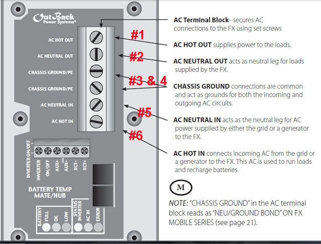
So what is connected to the terminal sets, #1 thru 3?
And what is connected to #4 thru 6??
There is an internal pass through of incoming AC through to the AC output. When that is active (when AC is coming from a generator or the power grid as noted in the image) the inverter puts DC power into the batteries instead of drawing DC from the batteries. At the same time the inverter also passes the incoming AC through to the AC output.
|
|
MtnDon
Member
|
# Posted: 25 Nov 2012 21:32 - Edited by: MtnDon
Reply
Quoting: Parrotdog ... for power to be accepted from the circuit panel which of course is connected to the load side of the transfer switch
This what confuses me most..... power goes to the circuit panel (service panel / breaker box) from the inverter terminals #1 & #2, not the other way around.
|
|
Parrotdog
|
# Posted: 28 Nov 2012 18:55
Reply
I agree, pictures help a lot.
Terminal 1 is routed to the FW500-AC Enclosure manual transfer switch wich continues to the bus bar feeding various circuit brekers
Terminal 2 routes to the enclosure neutro bus bar
Terminal 3 route to the enclosure chasis ground
Terminal 4 is empty
Terminal 5 is empty
Terminal 6 is routed to a circuit breaker on the DIN mounting bracket on the enclosure which then connects to the -alternate power source in- buss bar
I have not yet removed the manual transfer switch .
I do have the auto transfer switch connected to the geneator via the alternative source input
I do have the auto transferee switch connected to the FW500-AC enclosure power in buss bar which than connects to the inverter via the protective circuit beaker.
At this time I can charge the battery bank by throwing the manual transfer switch, turning on the protection circuit breaker, and pushing the manual start button on the auto transfer switch.
I have not yet connected the aux terminal on the inverter to a relay that would start the generator and consequently activate activate the auto transference switch.
If I understand correctly, terminal 1 & 6 are connected internally, than I do not think I have a problem, I just did not have the confidence to make that jump with what literature I was given with the system components.
Do you think it will be correct if I make the following changes:
Hook up the aux terminal as described above.
Remove the manual transfer switch.
Reroute the wire from terminal 1 to the prefered input on the auto transfer switch
Reroute the wire from the load side on the auto transfer switch to buss bar feeding the DIN mount breakers
Reroute the wire connected to terminal 5, via the protection circuit breaker, to the buss bar feeding the DIN breakers
You are very generous spending the time to help with this. I hope what I have written above is clear to you.
Thanks again for your help, Mark
Ps, when I finish this I will be able to comfortably drive my electric car to and from our "get away from the rat race" home. The vehicle has a range slightly under the round trip distance.
|
|
MtnDon
Member
|
# Posted: 28 Nov 2012 20:49
Reply
I have not worked with the FW500-AC type enclosures and feel at a disadvantage when you refer to things like "circuit breaker on the DIN mounting bracket on the enclosure ".
The absence of any connection to term 5 also throws me. 
|
|
Anonymous
|
# Posted: 4 Dec 2012 18:56
Reply
I emailed them and did not get a responce but I will call.
Thanks again for your replies. When I get an answere I'll post it.
Mark
|
|
|
