|
| Author |
Message |
CamaroMan
Member
|
# Posted: 26 Oct 2025 12:45pm
Reply
Hi all - just finished setting the 12 piers for our small single story cabin- the soil is rocky and the tallest pier is 3ft, rest about 2ft and 1 foot respectively as grade changes. I noticed the next day that if i push hard enough I can move the top. The soil is VERY rocky and superbly hard to dig (we used lances and dug by hand because no auger could handle it). it is VERY strong and nothing will go down (this is the top of a mountain). Rocks are 2-3" average with some 3-4" mixed with dirt..
Options / thoughts?
Once the beams are laid down and bolted down i do not see them moving however I am concerned- should there be more lateral strength? ie should be set them deeper?
|
|
Grizzlyman
Member
|
# Posted: 26 Oct 2025 04:15pm - Edited by: Grizzlyman
Reply
I am not certain how you would fix this CORRECTLY.. BUT bracing them diagonally would be the fix if they can’t compress any more or move down, then this would take care of of it. Maybe you could use 2xs and anchor into concrete at the base…or if you wanted beefier some angle iron or steel with a turnbuckle to do it.
I don’t know if demo and re-pouring would fix it since you can’t dig any deeper.
|
|
MtnDon
Member
|
# Posted: 26 Oct 2025 04:42pm - Edited by: MtnDon
Reply
I am not an engineer, but I believe this is why piers are not an approved, listed prescriptive foundation in the IRC.
I do not believe a depth of 16" is deep enough even if the frost depth is less than that, especially with some piers sticking out above grade by 3 feet. That 3 feet is a long enough lever that I would expect to be able to move the upper end.
It seems to me that a very rigid connection is needed between the pier top and the beam resting on the upper end of the pier to prevent wind forces on the building from causing any possible movement.
As a disclaimer, I will admit to having built our cabin on piers. Our piers are true 6x6 and 42 to 44 inches deep in a packed field of volcanic pumice. Piers extend 14 to 22" above grade. The pumice is well packed and drained with sizes ranging from sandy to 1 to 2 inches. (It is possible to dig or bore a hole 7 feet deep and not have the vertical sides slip or crumble) We are on a ridge top at 8755 feet and gusts of 40+ mph during storms are common.
I added shear walls constructed between the end piers (sideways) and some of the lengthwise piers for added rigidity of the foundation structure after having some discussions with an engineer I met after the build.
|
|
CamaroMan
Member
|
# Posted: 26 Oct 2025 05:38pm
Reply
Will be adding shear walls yes we get some wind. To dig deep enough would take ages- neighbor finished his contractor courses and self built and said it shd be fine - but I’m doing research. Upper side of cabin is into solid bed rock we had to jack hammer. .
Beams are tied in with the strongest Simpson ties and 1/2” bolts- the whole place would have to lift off to move basically-
|
|
DRP
Member
|
# Posted: 26 Oct 2025 07:43pm - Edited by: DRP
Reply
What Mt Don said. Note design responsibility. Fire the engineer 
R404.1.9.3 Masonry piers supporting braced wall panels.
Masonry piers supporting braced wall panels shall be designed in accordance with accepted engineering practice.
Look a section or two before that reference at "pier and curtain wall" foundations. That is the non engineered, approved, way of doing shear walls. In the south that is a common wall between piers done in brick. All on a strip foundation.
I'm guessing there are no footings on the piers or is it not connected to the footing?
Prescriptively, the underlying thought in the code is that the bracing wall panels above (Your sheathing braced exterior wind resisting walls) have collected the roof lateral load along the top plates of the sheathed walls that resist the load. The sheathed floor diaphragm braces the walls in square and distributes the lateral load from wind or shake to the bracing foundation walls. Braced walls over foundation walls.
A non-approved curtain wall could be treated ply for the bracing nailed well to a 2x4 treated lumber frame to prevent the ply from bucklng out of plane under load. Hammer drill through the end studs into the piers and use Simpson Titen screws to secure the panels between piers.
Someone posted a pic a bit ago of a leaning pier. Things start a cycle when they lean. When vertical the load is running vertically down the post. When a lean begins there is a horizontal component to the load pushing on the side of the pier 24/7.
Design wise, you can imagine drawing a triangle of the pier as it leans, a plumb line through the point of rotation, as you see somewhere below ground, and the horizontal beam at the top. The proportions of the vertical and horizontal legs of that triangle are the proportions of the load that has become vertical and horizontal. As the lean increases the upper leg gets longer in proportion to the plumb leg, and in real life as the pier leans, it doesn't take much to hold it, but as it continues to lean it gets harder and harder to keep it upright.
|
|
gcrank1
Member
|
# Posted: 26 Oct 2025 08:06pm
Reply
As in, 'the leaning tower sooner or later tumbles'?
|
|
MtnDon
Member
|
# Posted: 26 Oct 2025 09:00pm
Reply
Quoting: DRP A non-approved curtain wall could be treated ply for the bracing nailed well to a 2x4 treated lumber frame to prevent the ply from bucklng out of plane under load.
Somewhere I have images of mine, but that folder is elusive. DRP describes what I did: 2x4 PT framing nailed between piers and sheathed with 3/4" PT plywood with closely spaced nails. Placed across each end between the end piers. Plus a 7 foot section of similarly framed and sheathed materials at each end of the long wall. In other words each of the 4 corners has a 90 degree corner of shear walls.
On the sidewall sections the plywood was nailed over the outside of the pier and the built-up beam on top of the piers as well as to the 16: OC framing. . The framing does not contact the soil and there is ample ventilation in the areas with no shear wall covered in metal skirting that hides everything underneath. I was under there a month ago; still nice and dry even after the rains.
|
|
Brettny
Member
|
# Posted: 27 Oct 2025 07:04am
Reply
All that digging, bracing and work to just essentially have blocks for a foundation. Why not just cut your losses now and use blocks?
|
|
|
CamaroMan
Member
|
# Posted: 27 Oct 2025 11:49am - Edited by: CamaroMan
Reply
hi all - thanks for the replies. to clarify i meant we will use shear sheathing on the wall corners - as its code here - i was concerned about the lack of vertical lateral strength on the individual piers..
The piers have concrete post anchors that the beams/girders bolt to-
Option 2 is to dig the base out wider and pour an additional 16" 3x3 footing with rebar to add stability around the current piers.
Once the cabin is up i dont see a way for it to move- attached is a pic, the upper side piers are literlay about 6" above ground - ie half the cabin is extremely stable- it would take a mag 7 earth quake to shake it loose from the bed rock- its just the lower side where i have one 3 foot pier and 4 2 foot ones-
|
|
CamaroMan
Member
|
# Posted: 27 Oct 2025 11:57am - Edited by: CamaroMan
Reply
Here are the footers from my web cam - the orange is into bedrock. Excuse the low quality pic-
As mentioned im running 3 rows of doubled 2x12x20 foot beams/girders across the 10 foot span at 8' spacing for 24ft wide-
Then followed by joists etc-
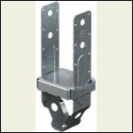
The beams are bolted to piers with simpson post ties for high loads using bolts -
Perhaps I can pin side supports either with 4x4s concreted into the ground or with concrete beams.
Hope that helps.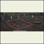
piers2.png
| 
C_PBST44Z_ProdPho_RI.jpg
|  |  |
|
|
CamaroMan
Member
|
# Posted: 27 Oct 2025 12:05pm
Reply
if i understand some of you correctly - another option would be to add side beams to the planned beams to square the lower girder frame up and possibly add some triangulation in the corners .. that would add strength to the 4 rows of beams additional to the joists/floor/walls.
|
|
CamaroMan
Member
|
# Posted: 27 Oct 2025 12:09pm - Edited by: CamaroMan
Reply
I was actually going to just stack blocks and pour concrete/rebar down both sides, even perhaps a square overlapping the blocks for strength, but i did not want to fight levelling them as the ridge is sloped- with the tubes you mark exactly at depth, cut/pour for a near perfect height. $100 bucks extra for incredible ease of use vs fighting with stacked blocks etc.
With blocks id have to first pour a level base at each post, then build with spec mix between blocks and hopefully end up with exact heights - just too risky and could snow ball out of control quite easy.
Was hard enough trying to figure out all the angles as it is already 
|
|
Grizzlyman
Member
|
# Posted: 27 Oct 2025 12:39pm
Reply
Already chimed in but diagonal/ cross bracing between piers seems like it would fix your issue. Especially if you’ve got a number of good piers already.
|
|
DRP
Member
|
# Posted: 27 Oct 2025 04:55pm
Reply
we will use shear sheathing on the wall corners - as its code here
You are bracing the framing with sheathing as per code, good.
i was concerned about the lack of vertical lateral strength on the individual piers..
And quite correctly.
The building code says those braced walls above sit on bracing foundation walls. They recognize what you just did and that is why piers are an engineer required method... this kinda shows why the code reads the way it does.
R403.1 General.
All exterior walls shall be supported on continuous solid or fully grouted masonry or concrete footings, crushed stone footings, wood foundations, or other approved structural systems that shall be of sufficient design to accommodate all loads according to Section R301 and to transmit the resulting loads to the soil within the limitations as determined from the character of the soil. Footings shall be supported on undisturbed natural soils or engineered fill. Concrete footing shall be designed and constructed in accordance with the provisions of Section R403 or in accordance with ACI 332.
What is bracing the piers you are happy with? I think you've seen the point of rotation is not the surface of the ground. The pier is not rotating around that 8" but at some point between there and its base.
The Simpson bracket footnotes say this;
Post bases do not provide adequate resistance to prevent members from rotating about the base and therefore are not recommended for installations that lack top support (such as fences or unbraced carports).
What you all keep building with these methods is the unbraced carport, there is no top support. I think you are trying to make a case that the deeper piers connected to the floor diaphragm supply the top support for the loose piers.
|
|
spencerin
Member
|
# Posted: 27 Oct 2025 09:17pm
Reply
I agree - add some type of diagonal bracing.
|
|
rpe
Member
|
# Posted: 31 Oct 2025 08:07am
Reply
OK, here's my thoughts after hand-digging about 20 piers over the years on our rocky Canadian Shield property:
16" deep? No footings? Did you probe down to find bedrock depth and profile in the area of each pier?
Imagine if bedrock is sloped steeply below the bottom of your wobbly piers. A vertical load on the pier may cause the bottom to slide down the sloped bedrock. Any movement at the pier bottom will result in eccentric loading, making matters worse. Frost heave if applicable also adds to the problem.
Digging by hand in rocky soil is miserable work, but can be done. Lift rocks and boulders out of the hole using an ATV winch, or manipulation with two shovels. A heavy wrecking bar can be used to smash up the bottom of the hole, and a large industrial shop vac to suck up gravel and small rocks. If you have a larger rock protruding into the pier hole that can't be removed, drill a series of holes and split it, or use an expansive grout like Dexpan.
Once found, clean bedrock surface, box up a large footing pad, and pin it to the bedrock with rebar. Extend rebar up the pier as well. If there's no bedrock at 5 ft depth, bell out the hole bottom to create a large footing. Reinforce with rebar and build your pier on that.
You may want to try the approach above on the corners at least. It might seem like overkill, but trying to fix pier issues after the building is sitting on top is NOT fun.
|
|
Brettny
Member
|
# Posted: 31 Oct 2025 10:00am
Reply
The 2x12 girder is going directly on the concrete? I think doing this will take out lots of the sway your feeling with a single post.
|
|
DRP
Member
|
# Posted: 31 Oct 2025 08:03pm
Reply
Again,
The Simpson bracket footnotes say this;
Post bases do not provide adequate resistance to prevent members from rotating about the base and therefore are not recommended for installations that lack top support (such as fences or unbraced carports).
|
|
Malamute
Member
|
# Posted: 31 Oct 2025 08:41pm - Edited by: Malamute
Reply
The code info keeps mentioning footers, it didnt sound like there were any footers under the piers. I had no idea anyone would pour a pier wirthout any footer under them, either concrete pad or better yet, the plastic footer forms known as bigfoot footers. The local lumber yard had them when I first started building and I used them on every pier or post I did. The hole has to be dug out larger enough, but a backhoe or mini excavator does that for the most part.
Ive hand dug holes for power pole fence posts, (up to 130 mph winds here) in hard packed rock and gravel. Using a 6 ft digging bar to break up 4-6" of packed ground, shovel to clean until it wont, then an angled WWII army shovel and small bucket down in the hole to herd the dirt into. Can reach 4 ft down with the old school folding army shovel and laying on the ground. 4' deep holes took between 1 1/2 - 3 hrs each of absolutely brutal work with 2 guys working. Still wouldnt try it for pier holes that needed footers.
Did my cabin on piers, all with footers, all 4' below grade. Backhoe or mini excavator is the only way id every try it with this ground.
Bigfoot footers https://bigfootsystems.com/index.htm
|
|
Brettny
Member
|
# Posted: 2 Nov 2025 05:57am
Reply
Quoting: Malamute had no idea anyone would pour a pier wirthout any footer under them
It's pretty common..if your calling a bigfoot a footing. All depends on the soil type though. In something like sand I would use a bigfoot. Here I have nearly rock hard packed clay. Going down to the frost line with a sono tube will be good.
|
|
DRP
Member
|
# Posted: 2 Nov 2025 08:52am
Reply
The code approval calls it a footing form.
My advice is to retain an engineer if you wish to proceed, or, remove that and put in a prescriptive foundation.
Sounds from the last comments like we are now hoping to pick up lateral from the footing.
Here is the language, they are not picking up lateral from the footing. We have left the IRC, this is from the IBC. This is deep but let's look at what the competent designer of this method is thinking about. The equations did not print, I'll stick them below.
1807.3.2 Design criteria.
The depth to resist lateral loads shall be determined using the design criteria established in Sections 1807.3.2.1 through 1807.3.2.3, or by other methods approved by the building official.
1807.3.2.1 Nonconstrained.
The following formula shall be used in determining the depth of embedment required to resist lateral loads where lateral constraint is not provided at the ground surface, such as by a rigid floor or rigid ground surface pavement, and where lateral constraint is not provided above the ground surface, such as by a structural diaphragm.
(Equation 18-1)(Equation 18-1)
where:
A = 2.34 P/(S1b).
b = Diameter of round post or footing or diagonal dimension of square post or footing, feet (m).
d = Depth of embedment in earth in feet (m) but not over 12 feet (3658 mm) for purpose of computing lateral pressure.
h = Distance in feet (m) from ground surface to point of application of “P.”
P = Applied lateral force in pounds (kN).
S1 = Allowable lateral soil-bearing pressure as set forth in Section 1806.2 based on a depth of one-third the depth of embedment in pounds per square foot (psf) (kPa).
1807.3.2.2 Constrained.
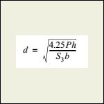
The following formula shall be used to determine the depth of embedment required to resist lateral loads where lateral constraint is provided at the ground surface, such as by a rigid floor or pavement.
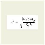
Equation 18-2.jpg(Equation 18-2)
or alternatively
(Equation 18-3)(Equation 18-3)
where:
Mg = Moment in the post at grade, in foot-pounds (kN-m).
S3 = Allowable lateral soil-bearing pressure as set forth in Section 1806.2 based on a depth equal to the depth of embedment in pounds per square foot (kPa).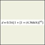
VACC2021P1_Ch18_Sec1.jpg
| 
VACC2021P1_Ch18_Sec1.jpg
| 
VACC2021P1_Ch18_Sec1.jpg
|  |
|
|
DRP
Member
|
# Posted: 2 Nov 2025 08:55am
Reply
I just noticed something in the text that I was taught early on when reading the code... pay particular attention to "may" and "shall". Wiggle room, or, only this way.
|
|
CamaroMan
Member
|
# Posted: 4 Nov 2025 02:15pm
Reply
hi all thanks-
to clarify yes the footing have bases with rebar and the beams lay on top as pictured
|
|
Brettny
Member
|
# Posted: 5 Nov 2025 06:04am
Reply
I think you will see them stiffen up quite a bit with then all connected via the girder and floor joists.
|
|
CamaroMan
Member
|
# Posted: 5 Nov 2025 11:11am
Reply
thats kind of what im hoping for once tied in the whole lot will be one.. virtually impossible to move in my opinion.
Will be using heavier duty ties as well- can always add a beam across the front and back to tie in the two outer rows of piers as well - ie a box beam setup vs traditional rows only..
|
|
|

