| << . 1 . 2 . |
| Author |
Message |
Don_P
Member
|
# Posted: 18 Aug 2015 10:02pm
Reply
I think what I'm seeing in the left hand picture would require engineering, a truss shop could probably do it cost effectively. As the tie is raised the forces on that connection rise and the bending force in the rafter at that connection need to be checked when the tie is raised more than 1/3 of the way up the roof height. I have code referenced tables that go up to half of roof height before an engineer is asked for.
If there is a ridgebeam then no tie is needed, the rafters are basically hanging from the ridge... if the ridge can't sag there is no thrust on the walls. That is a simple solution when it can be done.
I've attached a sketch I had that shows one way to tie the rafter feet together while still getting a loft kneewall, a ridgeboard works here, basically an attic truss that would be prescriptive codebook.
|
|
Don_P
Member
|
# Posted: 18 Aug 2015 10:14pm - Edited by: Don_P
Reply
Quoting: Zukowski Ive been looking up balloon framing and the sill plate is bolted to the concrete. Do I just build a subfloor and put osb on then attach my sill plate to that?
Typically a mudsill is bolted to the foundation walls. The floor rim joists are toenailed to that, the joists are also toenailed to it, Then subfloor then the wall sole plate is nailed to the subfloor and joists. The exterior wall sheathing is what ties all of that together. I typically hang the osb wall sheathing below the bottom of the mudsill about half an inch. Nail the wall sheathing to the mudsill very well then to the floor rim and studs. Block any edges that don't fall on framing. The entire perimeter of a sheet should land on framing of some sort, connectiong all the sheets together into a single plane.
|
|
Zukowski
Member
|
# Posted: 19 Aug 2015 02:09am
Reply
Quoting: DaveBell Attic Truss Vs Loft, You have to put on a roof, why not engineer for better space.
Well I thought about not doing a loft at all and just put a simple roof on but that leaves a bunch of unused spaced and I figured why not put a loft up there that would support my little girls as they grow up or a buddy or two when we go up north.
I know how to use tools I just dont now about building so i figured no need to engineer it if I keep it simple, but this is anything but simple.
|
|
Zukowski
Member
|
# Posted: 19 Aug 2015 02:20am
Reply
Quoting: Don_P Typically a mudsill is bolted to the foundation walls. The floor rim joists are toenailed to that, the joists are also toenailed to it, Then subfloor then the wall sole plate is nailed to the subfloor and joists. The exterior wall sheathing is what ties all of that together. I typically hang the osb wall sheathing below the bottom of the mudsill about half an inch. Nail the wall sheathing to the mudsill very well then to the floor rim and studs. Block any edges that don't fall on framing. The entire perimeter of a sheet should land on framing of some sort, connectiong all the sheets together into a single plane.
Cool, after I read that a second time I realized that i understood what your talking about. Im learning!
|
|
Zukowski
Member
|
# Posted: 19 Aug 2015 02:24am
Reply
This brings up another thought yet again, should I build on skids to ride to freeze or should I dig posts past frost line? I cant use a slab because i wont have heating most of the winter.
Like I said Im willing to contract some work out, so its either the roof or the foundation.
|
|
Don_P
Member
|
# Posted: 19 Aug 2015 07:40am
Reply
My preference is always a full perimeter foundation with footings down below the frost line. This prevents uneven up and down movement through freeze/thaw cycles. Being bolted to a full perimeter of walls also braces the structure horizontally and ties it down during high wind.
As long as the building is small enough that its' skids are one unbroken length, I'm not opposed to building that way. A gravel bed is a good foundation if the gravel is contained, a built up crib or stone retaining wall well outside of the building footprint is more stable than trying to perch on piers. The gravel can be built up to frost depth for that matter, just another way of thinking about things. As a building gets longer or wider and is built on a foundation that can move it becomes more difficult to keep it level in all planes and trying to relevel isn't easy. A good solid base works better. If the alternatives were better, guys like me would be all over it. I'd love to get out of the mud quicker and cheaper.
One line of thinking that I see pretty often is that these buildings are small so don't need to do X or Y. the width and length are often smaller, the height really doesn't change that much. A building that is narrow and tall is at risk of overturning in high wind. I'd rather slide than roll any day. Getting off of piers is a big help there as is building lower and wider.
|
|
Zukowski
Member
|
# Posted: 20 Aug 2015 01:42am - Edited by: Zukowski
Reply
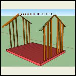
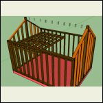
Alright Don, I think I have this finally. Things aren't perfect because im new with sketchup but it give you a good idea.
12*16 with a Loft
2*8s for the floor joist
2*6's for the walls
2*8's for the rafters
2*6s/8s for the loft joist
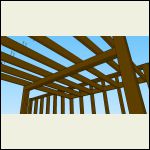
dont know how thick the loft beam needs to be so i still have to figure that out.
My beam ridge beam is 2x8 because i did it wrong but will fix it later when i add windows and doors, havent figured out a floor plan.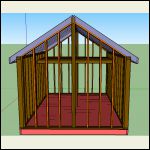
front.png
| 
balloon_walls.png
| 
Loft.png
| 
loft_beam.png
|
|
|
Zukowski
Member
|
# Posted: 20 Aug 2015 01:45am
Reply
Last 2.
|
|
|
Don_P
Member
|
# Posted: 20 Aug 2015 07:14am - Edited by: Don_P
Reply
The loft beam is carrying half the loft load... halfway towards the ledger on each side of it, so 6' of width for the 8' of length, or 48 square feet. The live load is 30 lbs per square foot, dead load is 10psf, total 40psf X 48 sf=~2000 lbs
Should be able to plug it all in from there;
http://www.timbertoolbox.com/Calcs/ddsimplebeam.html
In your rafter pic, technically the birdsmouth notch cannot be deeper than 1/4 of the rafter depth... just another thing as you redraw.
|
|
Zukowski
Member
|
# Posted: 21 Aug 2015 01:45pm
Reply
Quoting: Don_P The loft beam is carrying half the loft load... halfway towards the ledger on each side of it, so 6' of width for the 8' of length, or 48 square feet. The live load is 30 lbs per square foot, dead load is 10psf, total 40psf X 48 sf=~2000 lbs Should be able to plug it all in from there; http://www.timbertoolbox.com/Calcs/ddsimplebeam.html
So i go to input my values and when i click show results nothing happens, I check all my inputs and they have values so im kinda stumped.
|
|
Rdkng07
Member
|
# Posted: 21 Aug 2015 02:15pm
Reply
Looks like you butted the loft joists up to the 2x that you eased into the wall studs.
I would put them on top of the 2x and nail into the wall studs.
|
|
Don_P
Member
|
# Posted: 21 Aug 2015 03:32pm
Reply
Good catch!
|
|
Zukowski
Member
|
# Posted: 21 Aug 2015 04:47pm
Reply
Quoting: Rdkng07 Looks like you butted the loft joists up to the 2x that you eased into the wall studs. I would put them on top of the 2x and nail into the wall studs.
Yeah that was stupid mistake, i was going to use joist hangers because i was scared of height but really all i need to do is drop my ledger board down further.
Thanks for reminding me, Ill make sure its not like that in my final.
|
|
Zukowski
Member
|
# Posted: 21 Aug 2015 05:01pm
Reply
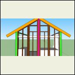
Heres my balloon framing with windows in, does it look like i missed something or need is there anything super wrong?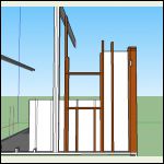
ballloon_frame_windo.png
| 
framing_ballon.png
|  |  |
|
|
Don_P
Member
|
# Posted: 21 Aug 2015 05:25pm - Edited by: Don_P
Reply
That is actually a requirement for that method...
Long winded warning, this goes a couple of layers deep.
Joist hangers have no load rating in the withdrawal direction, A joist has no tension capacity in a hanger connection, A strap can often solve that.
The joists tie the floor diaphragm to the wall when the joists pass over the ledger and are nailed to the wall studs. Now look up at the roof in that figure in the codebook, the rafters are clearly tied by the ceiling joists that are directly nailed across the rafter feet. The joist to stud connection is not a rafter thrust restraint connection in what they are describing.
At the end of the rafter span tables is a table of heeljoint connections. For various roof pitches, widths, loads and framing material they have specified how many nails to put into the connection tieing the rafter feet. Then in the footnotes to that table there are adjustment factors to multiply the required number of nails by to increase the tie strength as the ceiling tie is raised.
Those tables are where I look up how to connect those roof parts together. When the rafter is sitting on a kneewall without a ridgebeam and without a tie across the rafter feet, first it needs to be well connected to the top plate of the wall, which needs to be well connected to the studs, but, here is where I was going in all this, the tie connection is now through that whole path and finally, the joist to stud connection. The drawing I did above allows that textbook tie to the joist out at the end of the overhangs, the load path is correct again.
That and, sliding a joist over a ledger is much more fun than hangers if you don't like heights.
There will be loft-ier days ahead 
|
|
Zukowski
Member
|
# Posted: 21 Aug 2015 07:14pm
Reply
haha, Loft-ier days ahead. Nice.
|
|
Zukowski
Member
|
# Posted: 21 Aug 2015 07:16pm
Reply
So i went through and re sketched my wall with the ledger and because i drop it it runs into my window header area. Am I able to nail or bolt the ledger to that header for that last foot and a half or am I forced to drop the length back a bit?
|
|
Don_P
Member
|
# Posted: 21 Aug 2015 08:39pm
Reply
The ledger is the header, continue it to the left till it rests on the jack stud. Nail through the king stud on the left side of the opening into the end of the ledger.
|
|
Zukowski
Member
|
# Posted: 21 Aug 2015 09:22pm
Reply
Quoting: Don_P The ledger is the header, continue it to the left till it rests on the jack stud. Nail through the king stud on the left side of the opening into the end of the ledger.
Will do, thanks.
|
|
| << . 1 . 2 . |

