|
| Author |
Message |
LoonWhisperer
Member
|
# Posted: 26 Oct 2014 05:25pm - Edited by: LoonWhisperer
Reply
Hey folks, I am encountering a wiring issue I hope someone here can help me make sense of.
I built a battery box for the cabin and to this point have successfully mounted and wired an inverter as well as a Blue Sea 12v adapter and Blue Sea Fuse Block.
The next phase of the project was to add one of those cheap voltmeters and a single throw toggle switch.
There is where things went south. For some reason a fuse blows instantly when the switch goes to the OFF position(??). I tried 3, 5, 10 and 20 amp fuses.
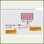
The voltmeter has 3 wires and the switch is just a two wire. I was told to join the red and white wire and attach it to the positive terminal of the switch.
The switch however is not clearly marked positive and negative and the data sheet does not make it clear either. From what I can see, the positive terminal is furthest from the ON position. I included a link and a picture of the switch.
URL
Thoughts on why this could be happening?
Thanks!
|
|
bldginsp
Member
|
# Posted: 26 Oct 2014 05:31pm
Reply
Can you provide us with a complete drawing of your wiring setup?
|
|
toyota_mdt_tech
Member
|
# Posted: 26 Oct 2014 06:05pm
Reply
I suspect the meter has a power, ground and maybe a display on?? Not sure. You should have the ground direct to the meter, the power interrupted by the switch. Technically, power goes to the input pole of the switch, be the center terminal. But backwards should make no difference on the switch, it just interrupts the circuit and ouput of switch goes to voltmeter.
|
|
MtnDon
Member
|
# Posted: 26 Oct 2014 06:14pm - Edited by: MtnDon
Reply
Quoting: LoonWhisperer The switch however is not clearly marked positive and negative and the data sheet does not make it clear either.
A simple SPST switch has no polarity. It is always placed in the hot wire in a DC circuit though.
It would help more to know what the three wires on the LED voltmeter are for. It only needs 2 to read voltage. Have you tried connecting the wires, a pair at a time to the battery pos & neg to see if you get a reading with the red wire to pos and the black wire to neg/ That is the usual polarity color when there is a black and a red.
Curious here... why the switch? I have a similar, albeit 2 wire, voltmeter, and it draws so little power when in use the switch is really not needed unless the battery has the capacity of a AA. A typical 12 volt car battery will lose power by self discharge faster than any LED will use it. Personal experience. The battery on the 12 VDC system in our converted cargo trailer has only dropped 0.06 volts in the past three weeks, as measured by a $$ Fluke meter. The LED voltmeter has not registered that change yet.
|
|
MtnDon
Member
|
# Posted: 26 Oct 2014 06:25pm - Edited by: MtnDon
Reply
A quick Google found this
Wiring:
red:power supply +
black:power supply -, measure -
white:measure +
So it's like the meter could be connected to a 12 VDC battery for a power source, but connected to a wire on a 5 VDC USB port to read a voltage measurement.
So red & white together to the battery positive and black to the battery negative. Try it without the switch, but with the fuse in the positive. (It's handy to have an assortment of alligator clip jumper wires).
Quoting: LoonWhisperer OFF position(??).
Why the ? marks?
If you have a multimeter, and you should, check the contacts on the switch. Does it really turn off and on... open circuit between the switch terminals in one position, completed circuit in the other position? Check ohms to see if there is a short between the switch metal case and the terminals. ...
|
|
LoonWhisperer
Member
|
# Posted: 26 Oct 2014 06:49pm - Edited by: LoonWhisperer
Reply
Thanks as always for the help fellas!
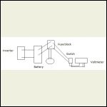
I attached a very simple sketch of how things are laid out. Not sure if it is useful.
The question marks are because I am not sure how switching the power to OFF would result in blown fuses. You would think that would happen when switched ON. For what it's worth, if the fuse goes in with the switch on, it works.
I wasn't sure of the draw of the meter so I put a toggle switch on it. Not mandatory if it's such a low draw I guess.
Basically I just twisted the white wire and red wire together and crimped them, is that correct?
Attached is a pic of the voltmeter wiring.
20141026_183749.jp.jpg
| 
_10.jpg
|  |  |
|
|
LoonWhisperer
Member
|
# Posted: 26 Oct 2014 07:26pm
Reply
Just to add... I tested the voltmeter with a 9v battery and it worked perfectly. So I guess I have it wired up OK. The issue must be with the switch and it's wiring.
|
|
MtnDon
Member
|
# Posted: 26 Oct 2014 08:07pm - Edited by: MtnDon
Reply
Just to be clear about wiring drawings.... The schematic illustrating the wiring is "off" I think. The photo up the link is an SPST switch (single pole single throw). That means the switch only has two positions (single throw) and only switches one wire (single pole). An SPST has only 2 terminals. The schematic shows a pair of incoming and a pair of outgoing. To someone used to reading schematics that schematic would be showing a DPST. To be correct the switch illustration should show only one wire from the meter terminated at the switch and one other wire connecting to the positive at the fuse block. The other wire from meter to fuse block would not touch the switch and would be the negative wire. In the real world that negative wire might connect together in the space occupied by the switch or the negative wire might be run more directly in a different route.
Hope that does not confuse things. Oh, the + and - should also be indicated someplace like at the battery at the very least. Sorry if that seems like nitpicking... that's a personal foible of mine I guess.
|
|
|
MtnDon
Member
|
# Posted: 26 Oct 2014 08:09pm
Reply
Quoting: LoonWhisperer I just twisted the white wire and red wire together and crimped them, is that correct?
As long as the wire terminal was sized correctly and well crimped, then insulated with tape or shrink tube if necessary. We don't want it to fall apart at some future time.
|
|
LoonWhisperer
Member
|
# Posted: 26 Oct 2014 10:04pm
Reply
Thanks Don! Based on your comments and some further research, it does appear I screwed up the switch wiring. I borrowed a pic on the net and modified it a little. Does this look correct?
|
|
MtnDon
Member
|
# Posted: 26 Oct 2014 10:29pm
Reply
 100% 100% 
|
|
razmichael
Member
|
# Posted: 27 Oct 2014 07:19am - Edited by: razmichael
Reply
late to this thread so I'm really only confirming by experience what has been generally figured out:
Quoting: MtnDon So it's like the meter could be connected to a 12 VDC battery for a power source, but connected to a wire on a 5 VDC USB port to read a voltage measurement.
Exactly. Given that the meter is designed to read low voltages, the display can be driven by a separate, constant power source. In this particular application, connecting the display and measurement leads to the main power will not cause a problem because, if the power source gets too low to drive the display you have other bigger problems! Also the impact of powering the display has such little impact on the actual voltage measurement.
Quoting: MtnDon Curious here... why the switch?
Fully agree that this is not really needed with respect to power draw. On the other hand, I have four displays and have not fully enclosed the control panel into the cabinet yet (way down the priority list) so I like having the switches so I can turn off the bright displays at night.
Slightly more complicated with the Ammeter as you also need shunts. In hind site I should have paid the extra bucks for the charge controller option with the LCD display and readouts - seemed like a good saving at the time!
|
|
MtnDon
Member
|
# Posted: 27 Oct 2014 10:00am
Reply
Quoting: razmichael Slightly more complicated with the ohmmeter as you also need shunts.
Don't complicate things when it's not necessary; shunts are not needed if all you're doing is checking continuity of a circuit or component like a switch. If you want to check amps being drawn, yes. Or a clamp meter may be easier for the non electrically inclined. Well, easier for the electrically inclined too as you don't have to mess with the wiring.
I agree the switch may be handy to kill the display at night if the light is bothersome.
|
|
razmichael
Member
|
# Posted: 27 Oct 2014 10:41am
Reply
Quoting: MtnDon If you want to check amps being drawn, yes.
Thanks - edited my post - originally said "ohmmeter" when I meant "Ammeter". I'm measuring the volts and amps from the panel and through the 12 volt circuits (hence the four displays shown in the picture).
|
|
MtnDon
Member
|
# Posted: 27 Oct 2014 11:26am
Reply
That clarifies things. I've been guilty of saving money up front and then regretting it later a few times too.
For a simple low voltage DC system where there are no huge loads a nice solution to the amps 'problem' is one of these meters.
the original
a copy
Actually two would be good as they only work in one direction; one for metering the charge from the PV to the battery and then a second for metering the power used from the battery.
I have a couple. I used one for a month or so to monitor and get a feel for the energy the 12 VDC fridge in the trailer used.
|
|
LoonWhisperer
Member
|
# Posted: 27 Oct 2014 11:55am - Edited by: LoonWhisperer
Reply
Thanks Don and everyone else that took the time to help out. Going to re-wire it all up this week and then will update.
Cheers!
|
|
razmichael
Member
|
# Posted: 27 Oct 2014 12:23pm
Reply
Quoting: MtnDon For a simple low voltage DC system where there are no huge loads a nice solution to the amps 'problem' is one of these meters.
I like the functionality of the "original". As you indicate - good for smaller loads. I see they have this rated at 100 amps peak and 50 continuous but, with 14 gauge wire, I would really be cautious using it at anything near 50 amps. Partially why I went with a big shunt even though I am measuring only the 12V circuit and not the 12v into the inverter (as this can pull a lot of amps).
|
|
MtnDon
Member
|
# Posted: 27 Oct 2014 02:05pm - Edited by: MtnDon
Reply
Quoting: razmichael I see they have this rated at 100 amps peak and 50 continuous but
Gotta remember the market this is aimed at; the RC (radio control) market. Electric RC airplanes and cars don't usually have a high draw for extended periods. Plus the batteries deplete rather rapidly when used under high load and that causes the available current rush to slow some. It does have 10 gauge wire leads IIRC.
I have used mine with loads up to 20 amps and it was 'happy'.
|
|
razmichael
Member
|
# Posted: 27 Oct 2014 02:13pm
Reply
Quoting: MtnDon Gotta remember the market this is aimed at; the RC (radio control) market.
Understood. The only manual/spec sheet I could find states 14 gauge leads but this was dated 2007. 10 gauge would give me more confidence using it in a slightly more demanding role. Too late for me anyway.
|
|
davidac
Member
|
# Posted: 3 Nov 2014 05:11pm
Reply
I am finishing a cabin in the woods, far from electric service... my plan is to have a generator (with a backup) for now, next year installing some solar... My idea is to fire up the generator in the morning for making coffee, cooking breakfast, running my wife's hairdryer, water pump, etc... at the same time I want it to recharge or top off the two 12 volt deep cycle marine batteries connected parallel... I have a 1000 watt inverter, and I just bought an automatic battery charger... my idea is that after a couple of hours using the generator in the morning, any further use of AC during the day will be from the inverter (coffee pot, slow cooker, computer, etc)... I also plan on having the lights 12 volt DC so they work even if the inverter goes kablooey... My question is, I want to hook up a fuse bar direct to the battery and run 5 to 15 watt CFLs and LED lights, only 5 or 6, and only one or two at a time will be on.. I was planning to use automotive fuses and wiring... problem is, I don't know what gauge wire to use, or what size fuses to use (longest run will be less than 30 feet).... hhhhhhhelp
|
|
LoonWhisperer
Member
|
# Posted: 13 Nov 2014 09:33pm
Reply
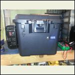
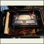
SUCCESS! Thanks for the help  
20141110_091007.jpg
| 
20141110_090849.jpg
|  |  |
|
|
|

