|
| Author |
Message |
Haltzy
Member
|
# Posted: 28 Sep 2015 07:23pm - Edited by: Haltzy
Reply
My fellow off griders; I'm in need of a no BS assessment of my off-grid system. Keep in mind this is my first attempt and have made mistakes throughout the process but this where I have ended up and would like you input.
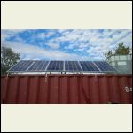
Image #1 Panels.
All PV are 12v 100 watt, I attempted to run in series at 24v but found the amperage was too low so I am now only running 5 of them parallel, as my CC will only take max 500 Watts. I thought running them at 24V would allow the extra PV but didn't work. All connection made with MC4 connectors and 10awg solar rated wire.
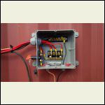
Image #2 Custom Combiner Box and Fuses
All wires coming from the PV to combiner box are 10awg. Wires going from the box to the CC are 8awg. Fuses are 30amp, I have been suspect of using fuses but is what I had. I I also put in a PV shut off switch as well.
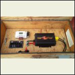
Image #3 - System Box
Picture shows CC, DC distribution panel and 1000W PSW Inverter. DC distribution feeds water pump, Outhouse lights, and a line going to my camper battery. I also have a 12vdc charging station in place. The DC distribution is fed from the Load out on the CC with automatic shut down. CC is rated at 500W12v/1000W24v MPPT 40Amp. (EBAY special)
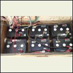
Image #4 - Battery Bank
Batteries located below sealed plate holding CC,Inverter and DC Distribution. The enclosure is well ventilated. 6x245Ah 6v batteries ran in series/parallel (3 12v banks) I have the negative tie in point in the top left and positive tie in point bottom right. All wires are 0 awg welding cable with soldered lugs. Both the CC in and Inverter out are on the same lug.
I appreciate the feedback.
Panels
| 
Combiner Box
| 
System Box
| 
Batteries
|
|
|
bldginsp
Member
|
# Posted: 28 Sep 2015 10:51pm - Edited by: bldginsp
Reply
-do you have a fuse on the positive battery lead as close as possible to the batteries?
-is your metal container connected to earth (grounded?)
-the 30 amp fuses seem large for the system. What is your operating amperage?
-are the fuses DC rated?
|
|
NorthRick
Member
|
# Posted: 29 Sep 2015 01:19am
Reply
Put pairs of panels in series for 24v and then the three pairs in parallel. Then you can use all six panels and get more power out of what you have. When you double the voltage, the amps will drop by half but the power remains the same.
That said, you have at least 2 different types of panels in that photo. They need to be pretty close to each other specification-wise to work well as a set.
|
|
creeky
Member
|
# Posted: 29 Sep 2015 09:44am
Reply
I would upgrade the controller to mppt 50 amps. that way you can use all your panels. also. you can "overpanel". This allows you to put more power into your batteries most of the time. as opposed to just when peak sunlight/temp occurs. So 600w on a 500w controller is perfect. the controller must be of sufficient quality to be able to handle overpaneling.
600w=12.7v X 50 amps (roughly)
or
600w=25.4v X 25 amps -- same thing. an mppt controller will convert your 24v input into 12v to charge the batteries.
Your batteries should share a common bus bar: the positive and negative from each 12v set should tie into its bus. this is to ensure that the batteries charge and discharge equally. try to get your cables to the bus the same length for each battery set.
you have quite a bit of power. a class T fuse of 300 amps between the battery and inverter is a good safety idea.
|
|
SE Ohio
Member
|
# Posted: 29 Sep 2015 09:49am
Reply
I'm a bit nervous about the (assuming flooded-type) batteries out gassing in such close proximity to the system box electronics. Separate boxes well-separated would be safer.
A schematic might be helpful for more specific feedback.
|
|
Haltzy
Member
|
# Posted: 29 Sep 2015 11:44am
Reply
Thanks guys,
To answer your Questions:
1- 30amp fuse between the CC and batteries
2 - Yes everything is grounded.
3 - 300amp fuse between battery and inverter
4 - Panels are the same.
5 - Batteries are flooded, but the bottom section of the box is well ventilated on both sides. no accumulation of gases.
I attempted to build a schematic. See Image #1
Really like the bus bar idea, will look into it. Any more ideas on this would be helpful.
|
|
creeky
Member
|
# Posted: 29 Sep 2015 12:28pm
Reply
there's a few posts here on battery connections. if you google it, there's a guy in britain who has posted the definitive guide.
you don't need a fuse between the cc and the batteries. but you do need a disconnect. you do need a fuse between the panels and the cc.
man it looks good. nice set up. you need a better cc tho. imho.
and if you've read any of my posts on small systems. Is that a pure sine inverter? For the cost...
|
|
Haltzy
Member
|
# Posted: 29 Sep 2015 05:10pm
Reply
I am running a pure sine wave inverter, it has done the job so far but will be replaced with a 24v inverter/charger eventually.
What size of bus bar would one need?
http://www.amazon.com/Blue-Sea-Systems-MaxiBus-Terminal/dp/B006VELFDK/ref=pd_sim_200_ 3?ie=UTF8&refRID=0AVDEJ0VE2KFTPMPZB8A&dpID=31f84fBeS6L&dpSrc=sims&preST=_AC_UL160_SR1 60%2C160_
I'm assuming it would be based on maximum wattage used by the inverter?
|
|
|
creeky
Member
|
# Posted: 30 Sep 2015 03:35pm
Reply
nice. I see you built some overhead in. a 1000 watt inverter is about 80 amps. so even double for surge 150 should do it. I see you have a 250 there.
if you can find a bus bar with 5 studs tho. one for each series pair battery, plus, one for the out to the inverter, plus, one for the in from the controller.
looking at 24v: note that 6 6v batteries can't be wired as 24v. You can do 4 6v or 8 6v (two strings).
and I would overpanel. you've got the panel. but I don't know what kind of cc you have. so. Morningstar has a fact sheet on overpaneling on their support page. might want to have a look.
|
|
Haltzy
Member
|
# Posted: 19 Oct 2015 01:01pm
Reply
Got my bus bars completed and installed. They look great and already have shown a more even balance when looking at the voltages from the inverter and the CC.
Swapped panels back to a 24v setup.
Thanks for the feedback.
Cheers.
|
|
|

